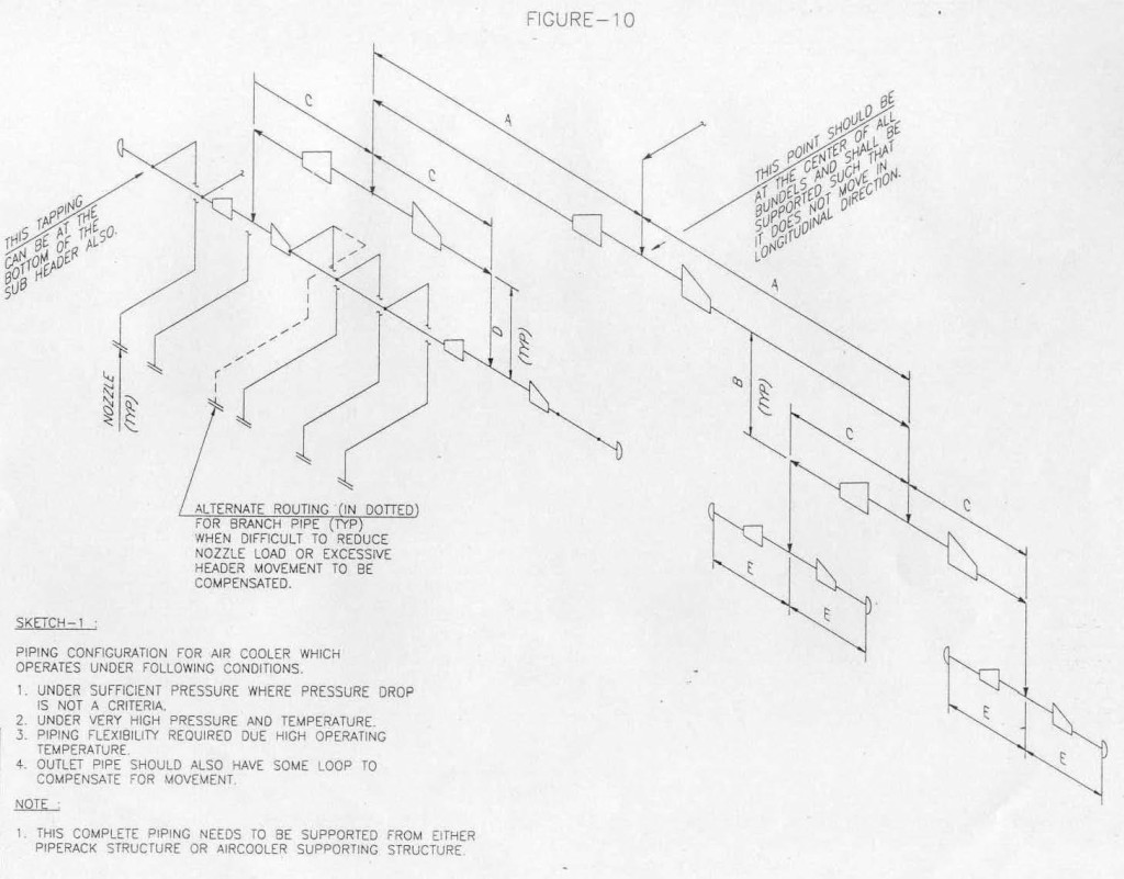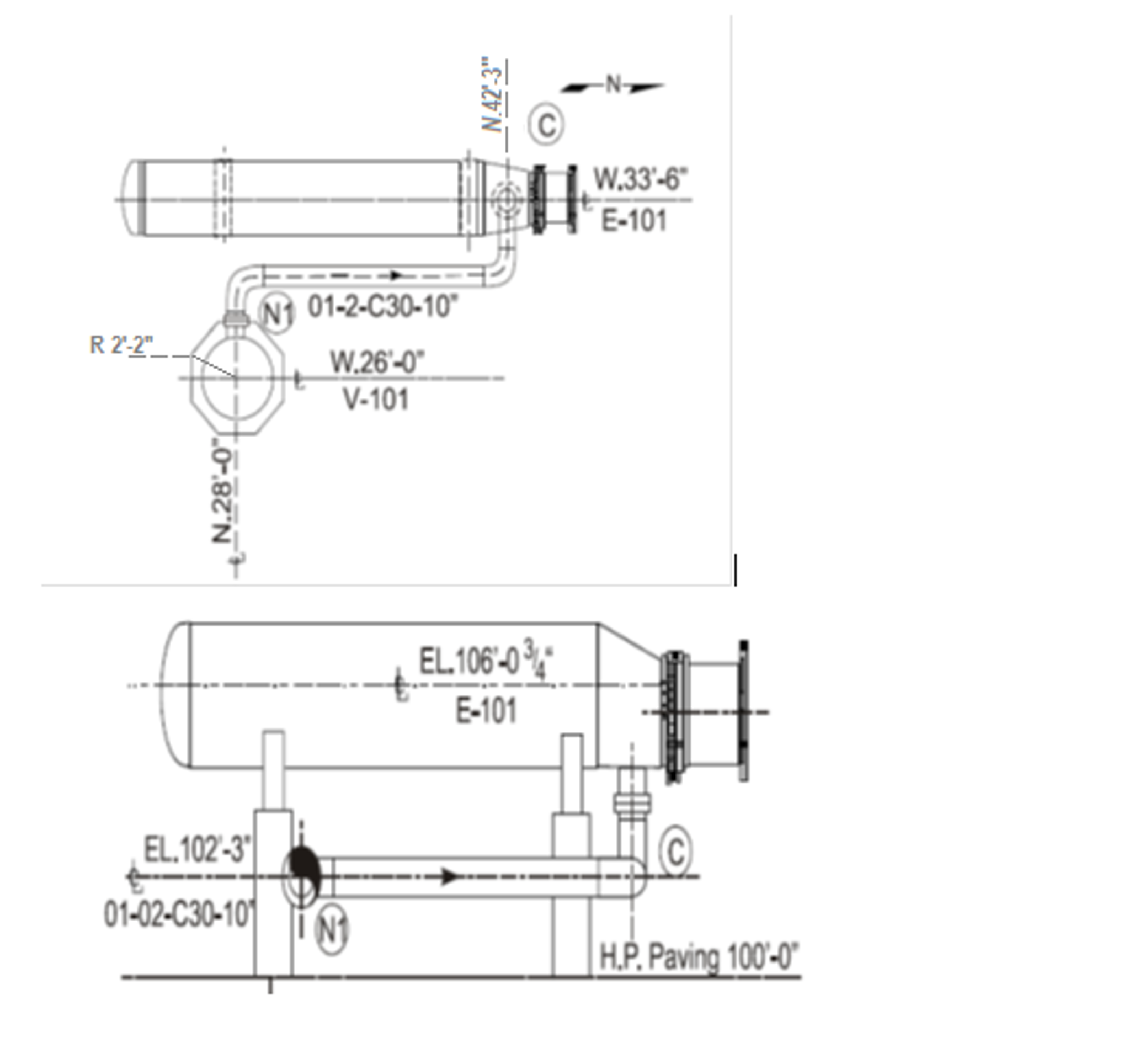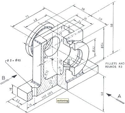


The isometric drawing is oriented on the grid relative to the north arrow found on plan drawings and not drawn to scale. Piping isometrics are usually drawn on a pre-printed paper, with lines of equilateral triangles form of 60°. Symbols like fittings, Valves and flanges are modified to adapt to the isometric grid. The Isometrics drawing are created from information found on a plan and elevation views. You can reset all the view at any point by choosing the Reset View button.In a piping isometrics drawing, pipe is drawn according to it’s length, width and depth, and often shown in a single view.

Rotate the entire figure by dragging the image or by using the sliders. The other buttons along the top navigation serve various functions: Simply select and drag the object(s) to a new location. When adding adjacent cubes, be sure to click on the face of the cube you want to be touching.Draw your shape from back to front and from bottom to top, to assure proper alignment of cubes.If your selection is red, on the grid, then it is a location where you can not place the object. Then, place the object on the grid where you want it.

Select the cube, face, or segment along the left navigation.


 0 kommentar(er)
